AVR ATmega32U4 with ENC28J60

Bare metal programming is an interesting activity that allows to get a new perspective for somebody that usually writes applictions for UNIX-like operating systems. Let's see how we can implement a driver for ENC28J60 ethernet controller from scratch and integrate a minimal IP stack to get some connectivity to the MCU.
Source code and toolchain setup:
- https://github.com/ltekieli/bazel_avr_tcp_ip/tree/master
- https://ltekieli.com/bazel-avr-toolchain-from-scratch-no_legacy_features/
References:
- https://docs.arduino.cc/hardware/micro
- https://ww1.microchip.com/downloads/en/devicedoc/atmel-7766-8-bit-avr-atmega16u4-32u4_datasheet.pdf
- https://ww1.microchip.com/downloads/en/devicedoc/39662c.pdf
- https://www.reichelt.de/arduino-netzwerk-schnittstelle-enc28j60-ard-net-enc28j60-p282716.html?r=1
UART Logging
Writing software with no to little feedback might be a big headache, especially when you have no debugger available. We can ease our work by providing a simple logging framework that will log messages using UART. Here's a code snippet of the desired functionality:
#include "log.h"
#include "timer.h"
#include "uart.h"

#include <avr/interrupt.h>
#include <util/delay.h>

int main()
{
    cli();

    timer_init();

    uart_init();
    log_uart_init();
    LOG_INFO("Logging initialzed!");

    sei();

    for (;;) {
        LOG_INFO_FMT("I'm %s!", "alive");
        _delay_ms(1000);
    }
}
Our requirements are:
- plain messages
- formatted messages
- timestamps
For timestamp support we can implement a simple interface:
#include <avr/interrupt.h>
#include <avr/io.h>

static volatile uint32_t system_tick = 0;

ISR(TIMER1_COMPA_vect)
{
    ++system_tick;
}

void timer_init()
{
    // https://www.arduinoslovakia.eu/application/timer-calculator

    // Clear registers
    TCCR1A = 0;
    TCCR1B = 0;
    TCNT1 = 0;

    // 1000 Hz (16000000/((249+1)*64))
    OCR1A = 249;
    // CTC
    TCCR1B |= (1 << WGM12);
    // Prescaler 64
    TCCR1B |= (1 << CS11) | (1 << CS10);
    // Output Compare Match A Interrupt Enable
    TIMSK1 |= (1 << OCIE1A);
}

uint32_t timer_get_system_tick()
{
    return system_tick;
}
TIMER1 is set up to trigger an interrupt every millisecond. The timer_get_system_tick() function will return the current "timestamp". Interrupts need to be enabled using the sei() function in our application code.
Now comes the UART setup code.
#include "uart.h"
#include <avr/io.h>
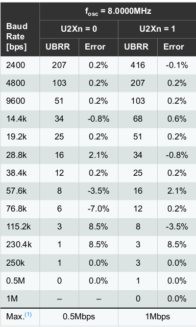
#define BAUD 2000000
#include <util/setbaud.h>
void uart_init()
{
// Set baud rate
UBRR1H = UBRRH_VALUE;
UBRR1L = UBRRL_VALUE;
#if USE_2X
UCSR1A |= (1 << U2X1);
#else
UCSR1A &= ~(1 << U2X1);
#endif
// Enable TX
UCSR1B |= (1 << TXEN1);
// Set 8N1
UCSR1C = (1 << UCSZ11) | (1 << UCSZ10);
}We are using the avr-libc built-in baud rate calculator. Arduino Micro is using a 16MHz clock so we can go as fast as 2Mbps for the UART speed:
With this setup, writing a single character requires waiting for the UDRE1 bit to be set in UCSR1A register and then pushing the character to UDR1.
int uart_putc(char c, FILE*)
{
    loop_until_bit_is_set(UCSR1A, UDRE1);
    UDR1 = c;

    return 0;
}
The signature takes additional parameter which is a FILE pointer. This is needed to fullfil the interface required for setting up standard output that can be used to support printf family of functions, which is the base of the logging.
Initializing our logging framework is limited to:
static FILE uart_str = FDEV_SETUP_STREAM(uart_putc, NULL, _FDEV_SETUP_WRITE);

void log_uart_init()
{
    stdout = &uart_str;
}
The generic logging function handles variadic arguments and adds a predefined prefix with a timestamp:
const char INF_PREFIX[] = "[%" PRIu32 "][INF]: ";
const char WRN_PREFIX[] = "[%" PRIu32 "][WRN]: ";
const char ERR_PREFIX[] = "[%" PRIu32 "][ERR]: ";

static void log_impl(const char* prefix, const char* fmt, va_list argp)
{
    printf(prefix, timer_get_system_tick());
    vprintf(fmt, argp);
    printf("\r\n");
}
In order to make the logging switchable, let's add macros that will hide the configuration:
#ifdef ENABLE_LOGGING

void log_uart_init();

#define LOG_INFO_FMT(fmt, ...) log_info_fmt(fmt, __VA_ARGS__)
#define LOG_WARNING_FMT(fmt, ...) log_warning_fmt(fmt, __VA_ARGS__)
#define LOG_ERROR_FMT(fmt, ...) log_error_fmt(fmt, __VA_ARGS__)

#define LOG_INFO(msg) log_info(msg)
#define LOG_WARNING(msg) log_warning(msg)
#define LOG_ERROR(msg) log_error(msg)

#else

void log_uart_init()
{
}

#define LOG_NOOP \
	do	         \
	{            \
    } while (0)

#define LOG_INFO_FMT(fmt, ...) LOG_NOOP
#define LOG_WARNING_FMT(fmt, ...) LOG_NOOP
#define LOG_ERROR_FMT(fmt, ...) LOG_NOOP

#define LOG_INFO(msg) LOG_NOOP
#define LOG_WARNING(msg) LOG_NOOP
#define LOG_ERROR(msg) LOG_NOOP

#endif
If ENABLE_LOGGING is defined, we will be able to see the messages on the UART, otherwise the logging is a no-op.
On the command line, enabling or disabling logging is controlled using a build configuration flag:
$ bazel build --config=avr --//:enable_logging=true //...The logging output is:
[0][INF]: Logging initialzed!
[0][INF]: I'm alive!
[1004][INF]: I'm alive!
[2007][INF]: I'm alive!
[3011][INF]: I'm alive!
SPI
Code for initializaing and using SPI can be almost taken 1:1 from the AVR datasheet. We will add additionally the chip (de)select functions, which needs to be called before and after transmission.
#include "spi.h"

#include <avr/io.h>

#define SPI_DDR  DDRB
#define SPI_PORT PORTB
#define CS       PINB0
#define MOSI     PINB2
#define MISO     PINB3
#define SCK      PINB1

void spi_init()
{
    // set CS, MOSI and SCK to output
    SPI_DDR |= (1 << CS) | (1 << MOSI) | (1 << SCK);

    // enable SPI, set as master
    SPCR = (1 << SPE) | (1 << MSTR);

    // F_osc / 2
    SPCR |= (0 << SPR1) | (0 << SPR0);
    SPSR |= (1 << SPI2X);
}

void spi_chip_select()
{
    // drive slave select low
    SPI_PORT &= ~(1 << CS);
}

void spi_chip_deselect()
{
    // return slave select to high
    SPI_PORT |= (1 << CS);
}

uint8_t spi_masterTxRx(uint8_t data)
{
    // transmit data
    SPDR = data;

    // Wait for reception complete
    loop_until_bit_is_set(SPSR, SPIF);

    // return Data Register
    return SPDR;
}
The SPI is configured to use the highest possible speed. Due to the characteristics of SPI, the transmission and reception can be implemented as a single function. Whenever a transmission occurs, one byte on master side is pushed out, and one byte is received from the slave. If we want to continously receive from a particular slave, the function needs to be called with a dummy byte.
Simple test program to read the revision from the ENC28J60 chip:
#include "enc28j60.h"
#include "log.h"
#include "spi.h"
#include "timer.h"
#include "uart.h"

#include <avr/interrupt.h>
#include <util/delay.h>

int main()
{
    cli();

    timer_init();

    uart_init();
    log_uart_init();
    LOG_INFO("Logging initialzed!");

    spi_init();
    LOG_INFO("SPI initialzed!");

    enc28j60_init();
    LOG_INFO("ENC28J60 initialzed!");

    sei();

    for (;;)
    {
        LOG_INFO_FMT("enc28j60 revision: %d", enc28j60_read_revision());
        _delay_ms(1000);
    }
}
[0][INF]: Logging initialzed!
[0][INF]: SPI initialzed!
[0][INF]: ENC28J60 initialzed!
[1][INF]: ENC28J60 revision: 6There is no real initialization needed in order to read the revision. Continue reading for details about ENC28J60 interfacing.
ENC28J60 driver
ENC28J60 communication happens through several SPI commands:
- Read/Write Control Register: RCR, WCR
- Bit Field Set/Clear: BFS, BFC
- Read/Write Buffer Memory: RBM, WBM
- System Reset Command: SRC
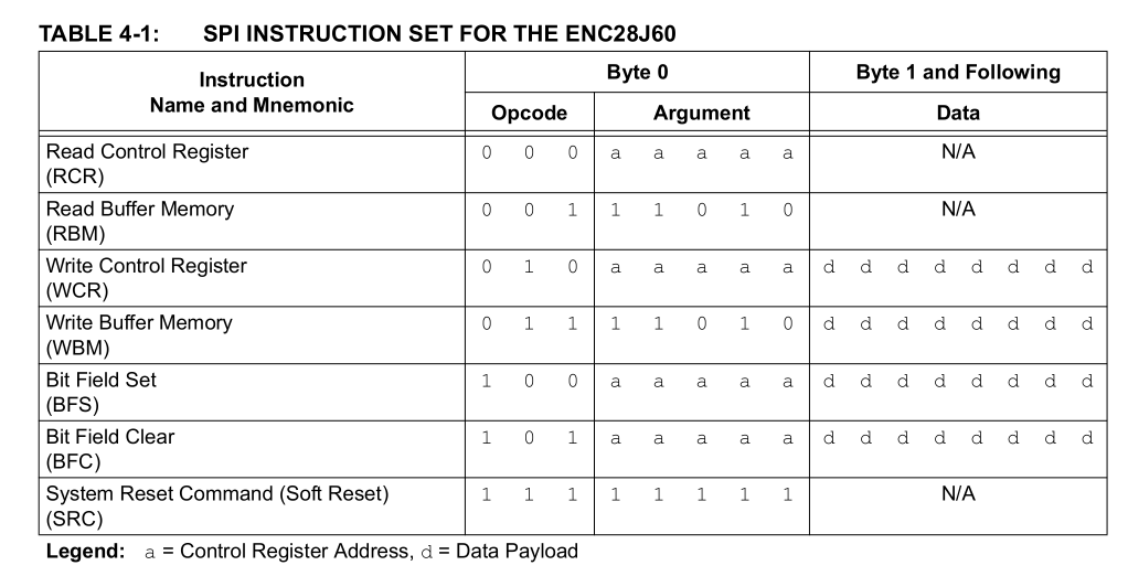
Essentially, it's either one byte with the operation code, or operation code followed by additional data.
The memory we can access through those commands is divided in 2 regions:
- registers
- etherenet buffer
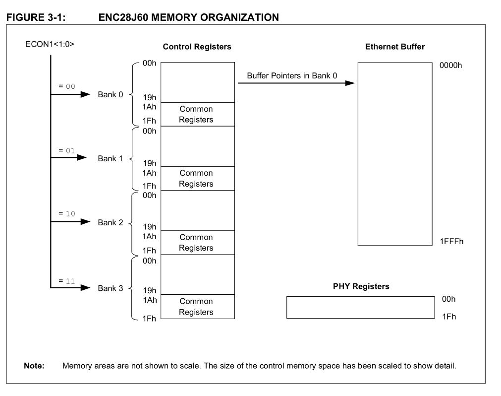
The PHY registers are accessed indirectly through a set of MII registers.
Reading and writing ETH, MAC and MII registers
The registers are organized in 4 banks:
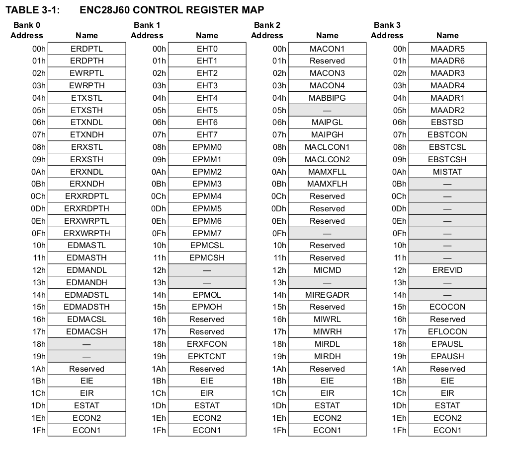
Accessing registers from a certain bank requires first switching to this bank. Each bank holds a set of registers that are common and do not require bank switching (0x1A - 0x1F).
Additionally there are 3 types of registers:
- ETH
- MAC
- MII
To read an ETH type register only one SPI command is needed. For MAC and MII two reads are needed:
static uint8_t enc28j60_spi_read(uint8_t opcode, uint8_t reg)
{
    spi_chip_select();

    spi_masterTxRx(opcode | enc28j60_get_address_from_register(reg));

    // Single read for ETH registers
    uint8_t result = spi_masterTxRx(0x00);

    if (enc28j60_get_type_from_register(reg) != ENC28J60_ETH_REGISTER)
    {
        // Double read for MAC nad MII registers
        // First byte read is dummy
        result = spi_masterTxRx(0x00);
    }

    spi_chip_deselect();

    return result;
}

static uint8_t enc28j60_read_register(uint8_t reg)
{
    enc28j60_select_bank(reg);
    return enc28j60_spi_read(ENC28J60_SPI_RCR, reg);
}
Selecting bank is implemented as follows:
static void enc28j60_spi_write(uint8_t opcode, uint8_t reg, uint8_t data)
{
    spi_chip_select();

    // Write the opcode + address
    spi_masterTxRx(opcode | enc28j60_get_address_from_register(reg));

    // Write the data
    spi_masterTxRx(data);

    spi_chip_deselect();
}

static void enc28j60_select_bank(uint8_t reg)
{
    enc28j60_spi_write(ENC28J60_SPI_BFC, ENC28J60_ECON1, ENC28J60_ECON1_BSEL1 | ENC28J60_ECON1_BSEL0);
    enc28j60_spi_write(ENC28J60_SPI_BFS, ENC28J60_ECON1, enc28j60_get_bank_from_register(reg));
}
One byte can be used to encode the register address, register type and bank number as follows:
- bit 7 - register type
- bit 6:5 - bank number
- bit 4:0 - register address
Reading and writing buffer memory
Accessing the buffer memory requires the usage of a different operation code. After that the data can be read/write sequentially:
static void enc28j60_spi_read_buffer_memory(uint8_t* data, uint16_t size)
{
    spi_chip_select();

    spi_masterTxRx(ENC28J60_SPI_RBM);

    for (uint16_t i = 0; i < size; ++i)
    {
        *data = spi_masterTxRx(0x00);
        ++data;
    }

    spi_chip_deselect();
}

static void enc28j60_spi_write_buffer_memory(uint8_t* data, uint16_t size)
{
    spi_chip_select();

    spi_masterTxRx(ENC28J60_SPI_WBM);

    for (uint16_t i = 0; i < size; ++i)
    {
        spi_masterTxRx(*data);
        ++data;
    }

    spi_chip_deselect();
}
Note that we didn't specify any start point or offset for the memory access. This is controlled by a different set of registers and it's directly coupled with setting up the RX and TX ethernet buffers. If those are set correctly, the reading/writing is then done based on this and an automatic wrapping is done by the controller itself.
PHY registers
PHY registers are not accessed directly, rather through the MAC. Those are 16-bit registers and require several SPI commands:
static uint16_t enc28j60_read_phy_register(uint8_t reg)
{
    enc28j60_write_register(ENC28J60_BANK2_MIREGADR, reg);
    enc28j60_write_register(ENC28J60_BANK2_MICMD, ENC28J60_BANK2_MICMD_MIIRD);

    _delay_us(11);

    while (enc28j60_read_register(ENC28J60_BANK3_MISTAT) & ENC28J60_BANK3_MISTAT_BUSY)
        ;

    enc28j60_write_register(ENC28J60_BANK2_MICMD, ENC28J60_BANK2_MICMD_MIIRD & 0x00);

    uint16_t mirdh = enc28j60_read_register(ENC28J60_BANK2_MIRDH);
    uint16_t mirdl = enc28j60_read_register(ENC28J60_BANK2_MIRDL);

    return (mirdh << 8) | mirdl;
}

static void enc28j60_write_phy_register(uint8_t reg, uint16_t data)
{
    enc28j60_write_register(ENC28J60_BANK2_MIREGADR, reg);

    uint8_t datal = data & 0xFF;
    uint8_t datah = data >> 8;

    enc28j60_write_register(ENC28J60_BANK2_MIWRL, datal);
    enc28j60_write_register(ENC28J60_BANK2_MIWRH, datal);

    while (enc28j60_read_register(ENC28J60_BANK3_MISTAT) & ENC28J60_BANK3_MISTAT_BUSY)
        ;
}
RX and TX Buffers
The ENC28J60 initialization consists of setting the boundaries of RX and TX buffers. There are two pairs of registers that needs to be programmed:
- ETXST/ETXND - start and end of the TX buffer
- ERXST/ERXND - start and end of the RX buffer
The available buffer spans from 0x0000 to 0x1FFF. For our application the TX buffer is set to 0x0000 - 0x0800, RX buffer to 0x0800 - 0x1800.
Additionally the ERDPT and ERXRDPT are set to the beginning of the RX buffer. The first one tracks the current read byte address. The second tells the ethernet controller what was the last read byte, so that it does not override the data with new packets.
Receiving packets
The steps to receive a packet are:
- check if there are any packets stored by reading hte EPKTCNT register
- read two bytes of RX buffer and form the address of next packet
- read two bytes of RX buffer and form the size of the current packet
- read two bytes of RX buffer and form the status for current packet
- check if the reception was ok
- read the amount of bytes from the RX buffer -> that's the packet
- advance the ERDPT and ERXRDPT
- decrement the packet count by setting the PKTDEC bit in ECON2 register
Sending packets
The steps to send a packet are:
- wait for pending transmission to finish when the TXRTS bit is cleared from ECON1
- if there's a transmission error reset the transmitter by setting and clearing the TXRST flag in ECON1
- set ETXST/ETXND according to the size of the packet
- set the EWRPT, the write pointer for the write memory buffer command
- write the data
- set the TXRTS bit in ECON1
Other initialization steps
There are several additional steps needed for initialization which are described in the datasheet. Compare the code against the datasheet to get more details. For our purpose most of the settings are kept as default.
At this point if the ENC28J60 is connected to an active ethernet interface on PC, packets can be received an dumped on serial:
[22359][INF]: [ENC28J60] rx packet count: 1
[22360][INF]: [ENC28J60] received packet size: 60
ff ff ff ff ff ff 60 7d 09 50 8f f4 08 06 00 01
08 00 06 04 00 01 60 7d 09 50 8f f4 c0 a8 00 01
00 00 00 00 00 00 c0 a8 00 02 00 00 00 00 00 00
00 00 00 00 00 00 00 00 00 00 00 00
This is an ARP packet sent from the host PC with arping:
$ arping -i enx607d09508ff4 192.168.0.2uIP integration
Being able to receive packets is only half of the job. Now we need some code to handles those packets and send responses. We will integrate the the uIP TCP/IP stack that is targeted for tiny MCUs:
It includes examples of simple "hello world" applications that can be enabled. We will just use a simple echo server.
uIP requires a header with configuration parameters:
Fortunately, the porting documentation for uIP contains all the necessary information:
The only architecture specific part at this point is to implement the clock source, for which we can use the previously defined tick function:
clock_time_t
clock_time(void)
{
    return timer_get_system_tick();
}
The communication between the driver and the uIP is done using the uip_buf and uip_len global variables representing the current packet buffer, which is used for both receiving and sending packets. Besides that, the appliction needs to call uIP API functions in the main loop.
Testing
With the above setup we can ping our small MCU:
$ ping 192.168.0.2 -c 4
PING 192.168.0.2 (192.168.0.2) 56(84) bytes of data.
64 bytes from 192.168.0.2: icmp_seq=1 ttl=64 time=21.3 ms
64 bytes from 192.168.0.2: icmp_seq=2 ttl=64 time=13.5 ms
64 bytes from 192.168.0.2: icmp_seq=3 ttl=64 time=13.4 ms
64 bytes from 192.168.0.2: icmp_seq=4 ttl=64 time=13.5 ms

--- 192.168.0.2 ping statistics ---
4 packets transmitted, 4 received, 0% packet loss, time 3005ms
rtt min/avg/max/mdev = 13.388/15.442/21.342/3.406 ms
Which is seen in the log:
[583827][INF]: [ENC28J60] rx packet count: 1
[583828][INF]: [ENC28J60] received packet size: 98
01 02 03 04 05 06 60 7d 09 50 8f f4 08 00 45 00
00 54 cc b1 40 00 40 01 ec a3 c0 a8 00 01 c0 a8
00 02 08 00 93 22 aa dc 00 04 97 2c 51 65 00 00
00 00 12 98 00 00 00 00 00 00 10 11 12 13 14 15
16 17 18 19 1a 1b 1c 1d 1e 1f 20 21 22 23 24 25
26 27 28 29 2a 2b 2c 2d 2e 2f 30 31 32 33 34 35
36 37
[583834][INF]: [ENC28J60] sending out packet size: 98
60 7d 09 50 8f f4 01 02 03 04 05 06 08 00 45 00
00 54 cc b1 40 00 40 01 ec a3 c0 a8 00 02 c0 a8
00 01 00 00 9b 22 aa dc 00 04 97 2c 51 65 00 00
00 00 12 98 00 00 00 00 00 00 10 11 12 13 14 15
16 17 18 19 1a 1b 1c 1d 1e 1f 20 21 22 23 24 25
26 27 28 29 2a 2b 2c 2d 2e 2f 30 31 32 33 34 35
36 37
And also test the echo application:
$ nc 192.168.0.2 1000
Hello. What is your name?
Lukasz
Hello Lukasz
Summary
As usual source code is the best place to find the details of the implementation. For getting things up and running it's definately enough, for getting full configuration of the ENC28J60, there's still some room for improvement :).